NET CLASSES
Overview
In Proteus a net class defines everything about how the nets assigned to it are to be routed. This information includes:
- The trace, neck and via styles to use, with a separate trace style and neck style for inner layers if you want them.
- The via type to use, either Smart or Thru-Hole.
- The colour of the class's ratsnest lines, and whether they are hidden.
- The testpoint rules for the class, either following the global rules or setting a minimum testpoint count of its own.
- Assorted controls for the auto router, including the layer pairs it may use and the priority it should give the class.
The beauty of encapsulating all these properties in a single entity and then assigning nets to it as opposed to assigning the properties separately to each net is that it greatly reduces the amount of information that need be entered on the schematic.
Net Classes and the Netlist
The assignment of a net class is made on the schematic by placing a wire label on a wire connection.
To create and configure a net class on the Schematic
1) Right click on the wire and select Place Wire Label from the resulting context menu.
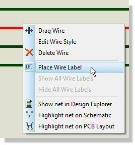
The Place Wire Label command on the wire context menu
2) Switch to the Net Class tab and click the New button to create a new net class.
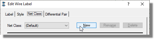
The Net Class tab of the Edit Wire Label dialogue, with the New button
3) Enter a name for the net class and then define the routing styles, via type, ratsnest display and testpoint rules on the dialogue form. For multi-layer boards you can specify different trace and neck styles for the inner layers of the PCB.
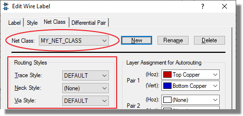
A new net class named MY_NET_CLASS with its routing styles set on the Net Class tab
4) Click the OK button to commit.
While it is necessary to define the net class on the schematic you can, if you prefer, leave the configuration of the net class (trace widths etc.) until you are ready to lay out the board. The same options are available from the Net Classes tab of the Design Rule Manager (Technology menu) in the PCB Layout module.
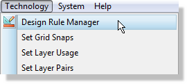
The Design Rule Manager command on the Technology menu of the layout module
See Also:
Routing Classes (Schematic Reference Manual)
Net Classes and Design Rules
Net Classes are extremely important in setting Design Rules for your layout. Once you have named a net class on the schematic and netlisted to the PCB module this net class becomes available as an option in the Design Rule Manager. This in turn allows you to control clearances between pads and traces for that net class by creating additional rules as required.
Since you can create as many net classes as you want it follows that you have the flexibility to control clearances on the PCB in as granular a way as is needed for your project.
See Also:
Design Rules and Net Classes (Tutorial)
Special Net Class Names
The most common reason for needing different net classes is to distinguish power connections from signal connections in order that the power routes can be made out of thicker tracking. Also, especially when using the autorouter it is often an idea if memory bus connections are given special treatment as they really need to be routed in an orderly, regular fashion.
In order to help with achieving the above distinctions, the net class names POWER, BUS and SIGNAL are given special meaning.
- Power nets normally arrive in the POWER net class without your doing anything. This is not a test on the net name: it comes from the power rail configuration on the schematic, where each supply carries a net class in its Class: field and the shipped defaults set that to POWER. Those defaults live in PWRRAILS.INI, and they are applied as long as the 'Use default power rail connections?' box on the Power Rail Configuration dialogue is ticked, which it is unless you clear it. In practice this means GND, VCC, VDD and the other usual supply names land in the POWER class of their own accord, and you can change the class of any rail on that same dialogue.
- The BUS net class is intended for memory bus connections and other nets that need to be routed in an orderly, regular fashion. Assign it by placing a bus label such as CLASS=BUS directly on a bus segment.
- All other net names default to the SIGNAL net class.
This scheme will enable many boards to be handled without need to explicitly specify net classes on the schematic or in the netlist.
See Also:
Power Rail Configuration (Schematic Reference Manual)
Editing a Net Class
Net Classes are created automatically by the Netlist Loader as their names are encountered. However, you will normally then need to edit them in order to set the various fields to whatever you require.
Net Classes may be edited using the Design Rule Manager on the Technology menu.